Quantcast
Channel: Wardy's Projects
Viewing all 70 articles
Browse latest View live

Rocket Surgery!

$
0
0
I am a late-comer to Kerbal Space Program.  For shame.

Been playing it for a week or two now and just now I managed to successfully dock two hand-built vessels in LKO (low Kerbin orbit).

To those unfamiliar with KSP, this may sound like a trivial accomplishment.  But no.  To do such a thing requires a lot of thought and sadly a lot of stout and stupid courageous Kerbonauts.  Bless them all.

I now have a fully functional (and extensible) space station in orbit and thus a platform to refuel and launch future long-distance missions from.

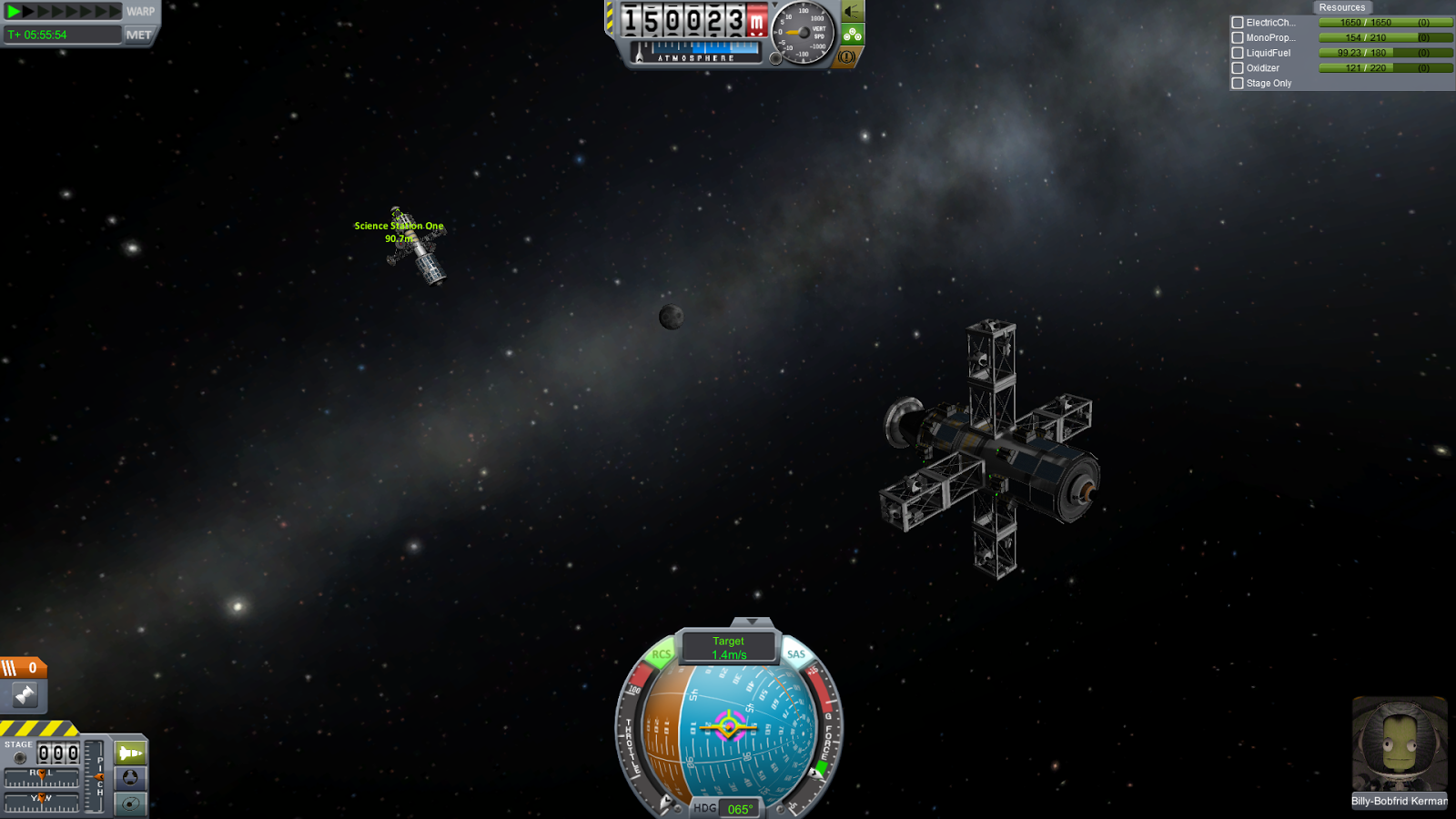
Here's a couple of screenshots from my mission...

Before docking (the main space-station vessel is on the left, the other ship is the "shunting wagon" which will perform refuelling duties)..


And a NASA press-corps image from after the docking process (which was fraught with stress and much fine-pitch thruster action)...


If you are a science nut like I am and love to learn about orbital mechanics, you should have a go at KSP.

Oh, and forget about going outside ever again if you do. :)
Knocking it out of the (osh) park!

$
0
0

www.oshpark.com


My "2049" game PCBs have arrived, a mere 17 days after I submitted the Gerber files!

As usual they look awesome.  The quality is top-notch and the gold plated copper on dark purple with white silkscreen is really eyecatching and distinctive.

Here's a picture to look at with your eyes...

oshpark (links to flickr.com viewer)

I was particularly impressed with the large complex pattern I had put on the bottomside silkscreen layer. To create that I did a basic pattern in MSPaint, took that into GIMP, rotated and blurred it heavily, then desaturated it and applied the "newspaper"filter to halftone the pattern into solid blocks of white. Then took that into Inkscape and traced it into vector format. Saved it as a WMF file and copy/pasted it into Diptrace.

Sounds complicated but it went very smoothly and took about 10 minutes.  The finished boards (to both OSHPark's and Diptrace's credit) look EXACTLY like the Diptrace 3D preview.

Super happy with these boards, and I cannot recommend OSHPark highly enough.  Spectacular job guys.

2049 Hardware Complete!

$
0
0
This is the finished board running the firmware that I originally wrote as an Xmas tree decoration...

2049 works

Looks better in real life than this photo would suggest :)

Electric Imp - Weather Display

$
0
0
Found a much better use for the 2049 board - a simple, cheap weather forecast display...

This picture shows an Electric Imp device delivering a 4x4 pixel image to the 2049 board from a server on the west coast of the USA...


The 4x4 pixel image itself is simply a debug image that proves that the system works.

The next step is to harvest weather data from the Met Office (Datapoint API) and have the server Agent convert this data into a series of animations for the 4x4 display to show.

By a weird coincidence the 2049 board is a perfect size for pairing up with an Electric imp dev board ("impee-april rev3").  That was totally unplanned!

The 2049 board uses about 60mA when running normal animations.  According the the documentation, the Electric Imp module uses no more than 400mA at any time.  So I can therefore simply bus the 2049 board and the EI board power  rails together and it will always be within spec for operation from a standard USB2.0 cable.

NOTE: the piece of paper in the above photo is only there because I found it very difficult to meter the chot correctly without it.  I guess the camera can't cope with point-light sources.  *shrug*

Propeller - high frequency output using CTRA

$
0
0
Here's a quick example of how to provide a high frequency output on a Propeller's GPIO pin.

Frequencies far above the actual CPU's clock speed can be generated with excellent resolution. In experiments I have found that 180MHz is achievable, although the signal degrades from a square wave to an approximate sine wave with reduced amplitude when measured directly on the Prop's pin.
The Propeller cog can set up this output and continue performing other tasks as the frequency generation doesn't take any run-time once initiated. The code below outputs a square wave at Pi megahertz (3,141,593Hz) by setting up Counter A in PLL single ended mode (00010) and setting FRQA to the value 10541436. This value is calculated using this equation...

FRQA = (DESIRED_FREQ_IN_HZ * (2^32)) / ((XTAL_FREQ_IN_HZ * CPU_PLL_MULTIPLIER * 16) / PLLDIV_MODE)

So, working this out using a standard 5MHz crystal, the highest PLL multiplier (pll16x) and a PLLDIV value of "divide by 1"...
10541436 = (3141593 * 4294967296) / ((5000000 * 16 * 16) / 1)
Setting the FRQA register to this value causes the Counter A subsystem in the current cog to output the desired frequency.
Each cog has 2 such counters, each of which is independent of the others. So if you wanted to you could output 16 different frequencies from the same chip while still using zero CPU time. Pretty cool.

CON
_clkmode = xtal1 + pll16x '80Mhz cpu speed
_xinfreq = 5_000_000


PUB main
coginit(0, @ASM_ENTRY_POINT, 0)

'----------------------------------------------
DAT
org 0

ASM_ENTRY_POINT
or dira,
HF_PIN 'set pin as output
mov FRQA, FREQ 'set up the desired frequency
mov PHSA, #0 'set the phase back to 0 (optional)
mov CTRA, CTRA_MODE
'begin output of the HF signal

waitpeq   $, #0 'sleep forever

'----------------------------------------------
HF_PIN        long      |< 15          'output on pin P15 (physical pin 20)
FREQ          long      10541436       '3.141MHz (see calculation)
CTRA_MODE long %0_00010_111_00000000_000000_000_001111


FIT


Turning the counter on and off in code will let you create a simple CW signal at your chosen frequency, if you have a Ham radio licence of course.

Changing the value of FRQA while the signal generation is running allows you to modulate the signal's frequency on the fly (as in FM radio)!

Casio 4723 (WVQ-550) wrist watch takes a CR1616 battery

$
0
0
Casio 4723 model watches (Wave Ceptor WVQ-550) require a CR1616 Lithium 3V coin cell.

As that information seemed to be entirely absent from the internet I have secreted it here for all eternity.

Get one off ebay and install it yourself or pay £10 for the nice person at H Samuel to do it for you. Either way the waterproofing rating will no longer be reliable.

Good watch though, eats a battery in 3 years though. Meh.

Where eagles dare...

[Ada Example #1] Statically linking C code into an Ada program

$
0
0
The following is intended to be a simple "hello world" style example of how to call a C function from Ada code.  I am using Linux (Debian Jessie, with the latest and greatest GCC v4.9.3 / Gnat v4.9.2 installed).

The C code and the Ada code are compiled separately and linked statically afterwards.

triple.c contains the C function I want to call from Ada...
//-----------------
#include <stdio.h>

int triple(int value)
{
  return value * 3;
}
//-----------------

test_prog.adb contains the Ada main program that calls the triple() function...
-----------------------------------------
with Ada.Integer_Text_IO, Ada.Text_IO;
use Ada.Integer_Text_IO, Ada.Text_IO;

procedure Test_Prog is
   type SInt32 is
      new Integer range -2_147_483_648 .. 2_147_483_647;

   function Triple (value : SInt32) return SInt32;
   pragma Import (C, Triple, "triple");

   A : SInt32 := 123;
   B : SInt32 := 0;
begin
   B := Triple (A); --  call the C function
   Put ("B is ");
   Put (Integer (B));
   Put_Line ("");
end Test_Prog;
-----------------------------------------


Makefile
all:
        gcc -c triple.c
        gnatmake -gnaty -c test_prog.adb
        gnatbind test_prog.ali
        gnatlink test_prog.ali triple.o

clean:
        -rm -f *.ali *.o b~*


It is also possible to do this the other way around - calling an Ada function from a main program written in C, but I suspect that this is a less common method.  The Ada program calls the C function and prints the correct result of 369.  Interestingly, the pragma Import lets you change the capitalisation on "Triple" which allows normal naming conventions in both C and Ada to be preserved.


Homebrew VHF Band Pass Filter

$
0
0
I've recently resumed my interest in radio technology after seeing the "SDRPlay RSP" device featured on a popular electronics website.  I bought one and then proceeded to be puzzled by the black magic that is Antenna Design.

A few small breakthroughs in understanding and I'm well on the way to taking the UK Foundation exam.  More on that in the coming months hopefully.

In the last few weeks I decided to build a band pass filter for my portable receiver and antenna to attempt to improve my reception of the spectrum between about 100MHz and 160MHz by suppressing everything outside that range, which contains Airband and some interesting Ham traffic.

The schematic and a photo of the finished article ...


To make this filter I used DipTrace to draw out the schematic which had already been tested using LT Spice software.

I then used DipTrace to generate a simple PCB design which I simply printed 1:1 scale on paper and used a scalpel to cut out the bits of paper where the copper pads would be (rather like a paper solderpaste stencil).

Then I taped that paper stencil to a piece of double-sided copperclad board and used a marker pen to draw the copper pads onto the copper.

Removing the paper stencil, I then drew a set of lines on the copper that showed the copper areas that needed to be removed in order to separate all the copper pads from the surrounding areas.

With this pattern finished, I clamped the copperclad to the table of my milling machine and used a small abrasive grinding bit to cut away the copper.

Once that was done I removed it from the mill, cleaned it with acetone and then soldered all the components on and tested it for short circuits.  There was one short where the grinding bit had left a tiny fragment of copper hanging over a pad but that was removed with a pair of tweezers.

Then I drilled a pair of holes in the copper board and mounted it into a die-cast aluminium Hammond enclosure to provide good RF shielding.  To finish off, I added some panel-mount RF connectors and coax to feed the signal in and out.

And happily I can report that it does behave exactly like LT Spice said it would!


SDR on Android with DVB adaptor

$
0
0

SDR on an Android 5.1.1 phone (OnePlus 2) using an "ezcap DVB-TFM DAB" dongle.

The app is called "RFAnalyzer" by Dennis Mantz, and is available for less than £1 (at time of writing) on the Google Play app store.

Source code can be found at https://github.com/demantz/RFAnalyzer.

I am thinking about writing some driver software to get the "SDRPlay RSP" receiver to work with this app, then this would really be fantastic for on the move listening.

Viewing all 70 articles
Browse latest View live